The Agenda
The academic curriculum differs from textbook to textbook, but in this website I'll list it in the order that I learned it.
This website should offer you (the readers) my experience in learning specific areas in physics, and it is to be used as a sort of a guide.
It is to be used for helping people 'understand', and I hope you achieve this after reading through all the text.
This website should offer you (the readers) my experience in learning specific areas in physics, and it is to be used as a sort of a guide.
It is to be used for helping people 'understand', and I hope you achieve this after reading through all the text.
The Academic Curriculum - the very basics (straight from the textbook)
A typical bar magnet has two poles. These are called N (north seeking pole) and S (south seeking pole) poles.
Like poles repel. Unlike poles attract.
Materials such as iron and steel are attracted to magnets. Magnets induce magnetism in them, and they become magnetized.
Iron becomes temporary magnets, while steel becomes permanent magnets.
Using this, you can make magnets by putting steel near magnets, or place it in a long coil of wire and pass a strong DC through the coil. (diagram 1)
The latter makes a much more powerful magnet.
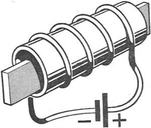
Diagram 1
A magnetic material is something which can be magnetized, and is attracted to magnets. These include iron, nickel, or cobalt (steel is 90% iron).
These strongly magnetic metals are called ferromagnetics (hard - steel / soft - iron) - (this term might not be used in all texts, but you should at least know it)
The properties of magnetism come from the very atoms themselves. The electrons moving around the nucleus creates a magnetic effect as it spins. In many types of atoms, these electrons cancel out each other's effects, but in magnetized objects these atoms don't. In this case, they all act like a tiny magnet, and unlike an unmagnetized material, these all point in the same direction, lining up with each other.
These atoms may be thrown out of line by being hammered, or heated up to a high temperature.
The Academic Curriculum - Intermediate - Magnetism
Okay, you've read the basics and mastered the basic principles, terms and the theory of the magnet. Now, we move on to the harder stuff.
Magnetic Fields
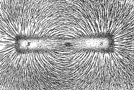
What are magnetic fields? To begin with, a magnetic field is the area in which the force of the magnet can reach. A magnetic field can be investigated with a compass. This basically means that if you put a compass next to a magnet, it will point to the direction of the magnetic field.
Then, there are field lines. A magnetic field line is a line which shows magnetic fields. Yeah, easy to understand, huh?
Let's put it this way. When artists are shading a sphere to give it a 3-dimensional kind of a look, they draw many lines when shading it, instead of just coloring it in.
Same here. The 'field' compromises of many lines, which adds up to an 'area'.
(Let me digress a little to explain it further. The definition of 'area' in mathematics is a mixture of a goddamn lot of lines. Same applies here I guess)
The field lines are just a small part of the infinite lines in the magnetic field itself.
Magnetic Fields
What are magnetic fields? To begin with, a magnetic field is the area in which the force of the magnet can reach. A magnetic field can be investigated with a compass. This basically means that if you put a compass next to a magnet, it will point to the direction of the magnetic field.
Then, there are field lines. A magnetic field line is a line which shows magnetic fields. Yeah, easy to understand, huh?
Let's put it this way. When artists are shading a sphere to give it a 3-dimensional kind of a look, they draw many lines when shading it, instead of just coloring it in.
Same here. The 'field' compromises of many lines, which adds up to an 'area'.
(Let me digress a little to explain it further. The definition of 'area' in mathematics is a mixture of a goddamn lot of lines. Same applies here I guess)
The field lines are just a small part of the infinite lines in the magnetic field itself.
The Magnetic Field Lines
The earth has a magnetic field (well duh how else would compasses work). But the way it is generated is a bit complicated.
I'm not sure this is in all textbooks, seeing as how it wasn't in mine, but I'll explain anyways.
Magnetic fields are generated when electricity flows through iron. Well, what's the core of earth compromised of? Metal.
The liquid metal of the outer core is relatively cooler than that of the inner core (still hot as the sun's surface though).
This causes the metal of the inner core to rise up to the outer core, switching places.
The movement of liquid metal generates electricity. Where would electricity go? It flows through metal, of course.
The core itself is metal, so the flow of electricity through it is the cause for the magnetic field. (this is called the geodynamo)
And that's how the magnetic field came to be.
The Academic Curriculum - Intermediate - Electromagnetism
When electricity is passed through a wire, a magnetic field is produced (very weak though).
Well, you can imagine how you make the simple electromagnets to understand this (you loop the coil around a nail or something).
This is where the Right-Hand Grip Rule comes in. There is no left-hand grip rule, funnily enough. Just remember that you use the right hand for this.
The Right-Hand Grip Rule states that the direction of the magnetic field produced by a current, when the thumb is pointing to the flow of the electricity, is that of the direction that your other fingers are pointing.
A diagram is worth a thousand words, I guess.
not very smooth, but it was the best I could find
Now, the magnetic field of coils can be added up to make a stronger one. Remember your elementary school electromagnet.
You know, the one where you wound some coils around an iron nail or something like that.
One loop doesn't make much of a 'magnet', but hundreds of loops will give you a pretty strong, if not average, one.
Using this, you can figure out the poles of an electromagnet. Put your fingers around the coil to the direction of the current, and your thumb will point to the N pole of the electromagnet!
Now that we've looked into the 'electromagnetism' itself, let's look at the magnetic force on a current.
In the diagram above, a wire is cutting between two magnetic poles. The electric current flowing in the wire creates a magnetic field around the wire.
There is a magnetic field in action already, and the field produced from the wire cuts in that field, creating disturbance. This disturbance is why you need to memorize another damn rule. Because a magnetic field is penetrating another one, it is pushed out, which is the force that we are supposed to learn. And Fleming's Left Hand Rule is a quick way (not really) to memorize that. But make sure you don't confuse it with the Fleming's Right Hand Rule, because it will have disastrous consequences.
The Fleming's Right Hand Rule is used when you track the electromagnetic induction in a wire. In other words, you use your right hand when you try to figure out which way electricity flows when you pass a wire through a magnetic field. Like the diagram above, you apply the force on the wire, making the disturbance in the magnetic fields into electricity. This theory is used to produce electricity, because it changes kinetic force into an electric force.
The Academic Curriculum - Intermediate High - Electromagnetic Induction
Electromagnetic Induction happens when a magnet/electromagnet is near a coil. It can either be in a form of kinetic energy or electricity, but in physics it is often (always, more like) referring to electricity. For example, when you move a magnet toward loops of coils, electricity is generated in the coils. In this case, the direction of the current is generated so that the magnetic field created by the current opposes the movement of the magnet. This is one of the easiest ways to make electricity from kinetic energy
There are many usages of electromagnetic induction, the most common being the motor. Look at the diagram below.
There are many usages of electromagnetic induction, the most common being the motor. Look at the diagram below.
How motors work is one of the most difficult things to understand here, but I'll try to explain it as best as I can.
The battery is connected to the carbon brushes above, which makes it possible for electricity to flow. The commutator then conducts electricity it receives from the battery to the coil, which makes an electric current. Because there is a new magnetic field made by the current, a disturbance in the original magnetic field created by the field magnets causes a force to apply on the coil. Keep in mind, however, that the direction of the force in the left part of the loop and the right part of the loop are different, so you should imagine them separately. In the picture above, if you use Fleming's Left Hand rule, a downward force is applied to the left side of the coil loop, and an upward one on the right. This causes the coil to spin counter-clockwise, which is the very basics of a motor.
This motor uses a single coil, which causes it to buckle while spinning, which would be hard to use. That's why practical motors have usually three different coils which are at different angles. (This is a terrible job of trying to explain. I will post a diagram below)

The left motor is a photo of a practical motor. The right one is a simple diagram to show how the coils are placed the minimize the 'buckle'
(I know, it's not the best diagram ever, but you can't do much when you're using MS paint)
Now, about the Right-Hand rule. This is used to GENERATE electricity, which is the very opposite of the motor.
If you've been to a power plant (a hydroelectricity power plant actually) you would have seen the turbine being spun by a force (water, steam....). This is because kinetic energy is one of the very few types of energy that you can change into electricity. The reasons for that being electromagnetic induction.
Look at the diagram below.

Not really the best diagram, but it was the best I could find.
How is this different from the motor? Well, this uses two slip-rings instead of one. And the brushes aren't connected to a battery. That's it.
This is how it works: You turn the wire loop, causing, for the final time, a disturbance in the magnetic field. Again, this leads to electricity being induced in the wire. Using the Fleming's Right Hand rule, we can figure out which direction the electricity will flow. And.... that's pretty much it, I guess.
If you still can't understand what I'm trying to explain here, try this site: http://www.animations.physics.unsw.edu.au/jw/electricmotors.html
It has animations to help you understand the theory of electromagnetically induced force (it's not a scientific term, but it shows what it means). I think it might be better than just words to actually 'see' it. A picture is worth a thousand words. Imagine how many words an animation is worth :)
Another usage of electromagnetic induction is the transformers. Transformers (for those who don't know) are tools that are used to 'step up' or 'step down' voltage. Why do you want to change the voltage, you ask? It's a bit complicated, but the basic theory is that the higher the voltage, the less power you lose during electricity transmit (between the power plant and your home). I will go deeper into this later, so make sure you read it. It is very very important, and disastrously tricky.
The way they work is quite simple, yet quite complicated. Basically, you wrap a coil around a left part of a metal square, and wrap another coil at the right part. If you flow an electric current on the left coil, there will be a current flowing on the right, with a voltage proportional to the number of loops of the primary coil and the secondary coil. This is more simple to explain by a diagram.
the coil on the left is called primary coil, and the one on the right is called a secondary coil
The thing about transformers is that they are very straightforward. The number of times you wrap the coil is the main thing that controls the output voltage. For example, if you wrap the wire 6 times on the left and 12 times on the right, and feed a current of 30 V to the primary coil, the output voltage will be 60 V.
As an equation, it would be V1/V2 = N1/N2 (V1/V2 = voltage of the current in primary/secondary coil, N1/N2 = number of loops in primary/secondary coil)
The theory of how this works is that the AC power supplied to the coil creates a magnetic field that continuously changes from N to S. This creates a charge at the ends of the primary coil, which then creates a magnetic flux
You will probably notice that step-up transformers will have more loops on the secondary than the primary, and step-down transformers the other way around.
However, there is another element that decides the output of the transformer, and that is its efficiency.
There are a few situations where energy is lost during the voltage changing process.
1. As a transformer changes voltage, some of the electricity flowing through the coil is met with resistance (you probably know that all forms of electricity transmit has a resistance measured in ohms), which turns some of the electricity into heat.
2. When a transformer is powered, the changing magnetic field induces 'Eddy currents' in the core which result in the loss of energy.
3. Also, the primary coil generates and a continuously alternating magnetic field in the iron core, losing energy in the process. This is called Hysteresis.
A good transformer minimizes the amount of electricity lost due to the three instances listed above. The method of minimizing energy loss is quite simple.
Since we cannot lower the resistance of the wire any further (price & conductivity), we can only try to reduce the total power loss during process 2 and 3.
To lower the power loss during process 2, the core of the transistor should be 'laminized' - that is, to cut the core into thin pieces and glue them together.
To lower the power loss during process 3, a soft iron core is used.
An 'ideal' transformer is one that does not lose any electricity while its step-up/down process, but in reality it does not exist.
This is because the resistance of a material can NEVER be 0.
